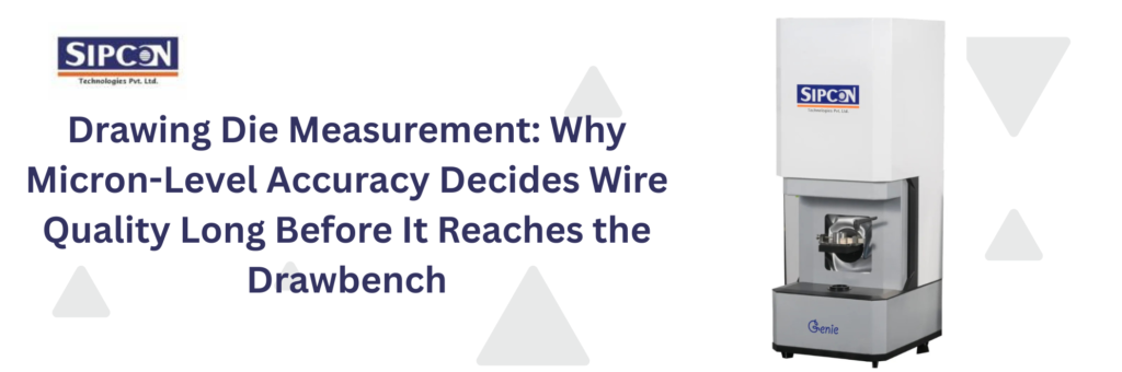
Ask any wire or tube drawing engineer where quality problems actually start, and the answer is rarely the drawbench itself. It’s the die. A bearing land that’s off by 5 microns, a nib that has gone slightly oval after a production run, or an approach angle that has drifted from spec — none of these are visible to the naked eye, yet every one of them shows up downstream as surface scoring, dimensional drift, excess heat generation, or premature die failure. This is precisely why drawing die measurement has moved from being a periodic quality-control task to a core part of die lifecycle management in wire, cable, tube, and fastener manufacturing.
At Sipcon Technologies, we work with die shops and wire producers across Italy and Europe who have learned this the hard way: a die that “looks fine” under a loupe can still be costing thousands of euros in scrap and downtime. Below, we break down what modern die measurement actually involves, how the technology works, and what to look for if you’re evaluating a system or a supplier.
What Drawing Die Measurement Actually Covers
A drawing die’s performance depends on several internal geometric features working together — the entry radius, reduction (approach) angle, bearing (land) length, back relief angle, and the nib diameter itself. Traditionally, shops measured these using shadowgraphs, pin gauges, or manual profile projectors. These methods work, but they’re slow, operator-dependent, and often incapable of resolving the internal bearing zone with the accuracy modern drawing speeds demand.
Drawing die geometry measurement today is expected to capture the entire internal profile — not just a few reference points — and present it as a true cross-section that can be compared directly against CAD drawings or previous inspection records. This is the difference between “the die passes inspection” and “we know exactly how much bearing length remains before this die needs re-polishing.”
How a Drawing Die Measurement Machine Works
A purpose-built drawing die measurement machine typically uses one of two approaches:
- Optical/laser profile scanning — a non-contact sensor traces the internal bore of the die, reconstructing the profile without physical contact that could wear or distort delicate polished surfaces.
- Contact/CMM-style probing — a fine stylus follows the internal contour for applications requiring extremely tight tolerance verification, often used to validate optical results on reference-grade dies.
The best systems combine speed with repeatability: an operator should be able to load a die, run an automated scan cycle, and get a full geometric report — angle, bearing length, diameter at multiple depths, ovality, and surface condition — within minutes, not the 20–30 minutes a manual shadowgraph inspection can take. For high-volume die shops running hundreds of dies per week, this difference alone changes the economics of quality control.
Drawing Die 3D Profile Measurement System: Seeing What Flat Inspection Misses
Traditional 2D shadowgraph inspection only captures the die profile along a single plane. But real dies — especially after wear, incorrect regrinding, or thermal stress from high-speed drawing — often develop asymmetric wear, meaning the bore is no longer perfectly round or the bearing length varies around the circumference.
This is where a drawing die 3D profile measurement system earns its value. By capturing the full 360° internal geometry rather than a single cross-section, it reveals:
- Ovality and out-of-roundness that a 2D projector simply cannot detect
- Uneven bearing length caused by off-axis polishing
- Localized wear zones that predict where the die will fail next
- True 3D comparison against the original CAD or master die, overlaying deviation maps in microns
For die manufacturers, this data isn’t just a pass/fail check — it’s diagnostic. It tells the polisher exactly where correction is needed, rather than relying on trial-and-error regrinding that can shorten die life.
Choosing the Right Drawing Die Measurement System
When evaluating a drawing die measurement system, the specification sheet matters less than how the system performs on your actual die range. Key questions worth asking any supplier:
- Diameter range — can it handle everything from fine wire dies (sub-1mm) to large tube-drawing dies without swapping fixtures?
- Repeatability — what’s the machine’s measurement uncertainty, and is it independently verifiable?
- Data output — does it generate a usable report format (PDF, CSV, CAD overlay) that fits into your existing QC documentation and traceability system?
- Cycle time — how many dies per shift can realistically be inspected?
- Material compatibility — does it work reliably on tungsten carbide, PCD (polycrystalline diamond), and natural diamond dies, all of which behave differently under optical scanning?
A system that excels on paper but struggles with your specific die geometry or material isn’t the right investment, regardless of price.
Evaluating a Drawing Die Measurement Manufacturer
Not every instrumentation company that lists “die measurement” in its catalogue has built the system specifically for drawing die applications. A specialist drawing die measurement manufacturer understands the metallurgical and process context — why bearing length tolerance in a fine-wire die is far tighter than in a heavy tube die, and why die material affects how light reflects off the bore during optical scanning.
At Sipcon Technologies, our systems are engineered specifically around this application, not adapted from general-purpose metrology tools. That distinction matters when you’re inspecting hundreds of dies a month and need consistent, defensible data — not just a measurement, but a measurement your engineering team can act on.
Drawing Die Measurement Machine Price: What Actually Drives Cost
Pricing for a drawing die measurement machine varies significantly based on a few real factors, not just brand:
- Measurement technology — non-contact optical/laser systems with full 3D profiling sit at a higher price point than basic 2D shadowgraph units, but deliver far more diagnostic data per die.
- Automation level — manual loading and alignment costs less upfront but increases labor time per die; motorized, auto-centering fixtures raise the initial investment while cutting cycle time.
- Software and reporting capability — CAD-overlay comparison, statistical trend tracking across a die’s service life, and multi-user reporting add value (and cost) beyond a simple pass/fail readout.
- Diameter and length range coverage — systems built to handle both fine-wire and heavy tube dies in one machine typically cost more than single-range units.
Rather than comparing price in isolation, it’s worth calculating cost-per-die-inspected over the machine’s service life, factoring in reduced scrap, fewer premature die replacements, and faster changeover — this is where a well-specified system typically pays for itself within the first year of use.
Talk to Sipcon Technologies
Whether you’re a die manufacturer looking to tighten quality control before dies ship, or a wire and tube producer wanting to extend die life through better wear tracking, our team can walk you through which measurement approach fits your specific die range and production volume.
Get in touch with Sipcon Technologies, Italy:
📞 WhatsApp: +39 340 404 2357 📧 Email: eu@sipconinstrument.com